Compound Direct Current (DC) Circuits MCQ Practice

Question 1 of 10

The figure shows R1 = 3 Ω in series with two branches: an upper R2 = 6 Ω and a lower R3 = 2 Ω followed by R4 = 4 Ω. An ideal 18 V battery supplies the network. What power is dissipated in R4?
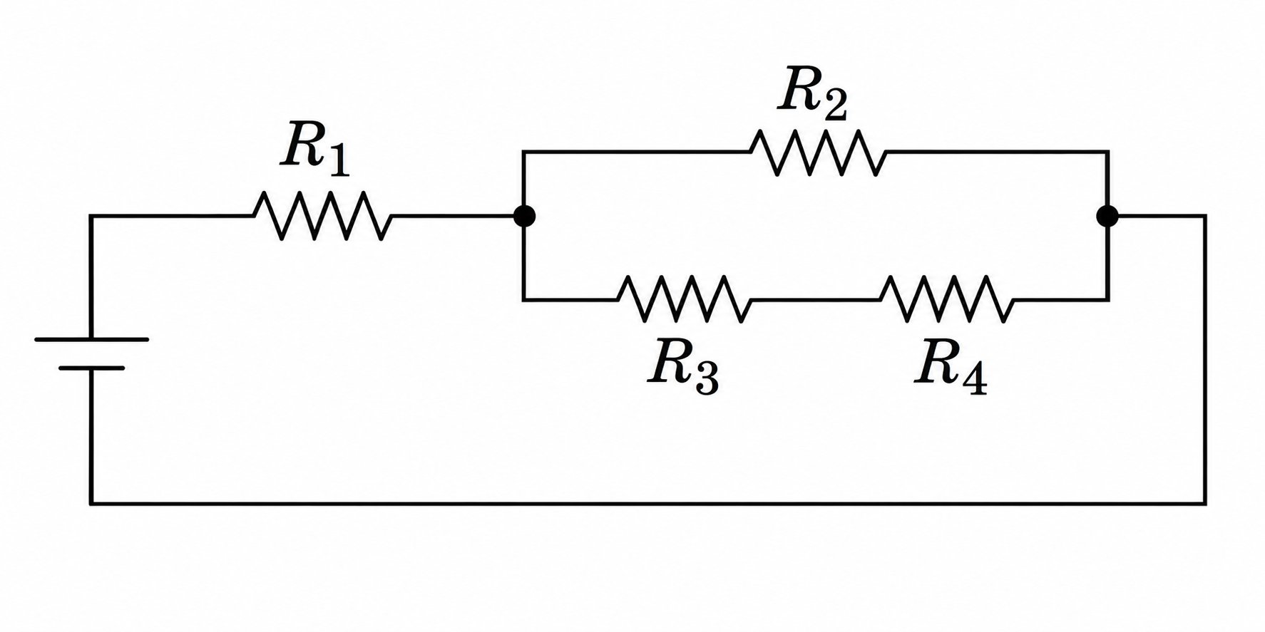
A battery and R1 in series with two parallel branches: R2 above, R3 and R4 in series below.
  1. A. 3 W
  2. B. 6 W
  3. C. 9 W
  4. D. 18 W

Question 2 of 10

In the same four-resistor circuit, an ideal wire is placed directly across R4. What is the ratio of new power in R2 to its original power?

A battery and R1 in series with two parallel branches: R2 above, R3 and R4 in series below.
  1. A. 4/9
  2. B. 2/3
  3. C. 1
  4. D. 9/4

Question 3 of 10

A battery's terminal voltage is 10 V at 1 A and 8 V at 2 A. It is connected to two 6 Ω resistors in parallel. What is its terminal voltage under this load?

  1. A. 6.0 V
  2. B. 7.2 V
  3. C. 8.0 V
  4. D. 9.6 V

Question 4 of 10

An ideal 12 V battery powers a 2 Ω and a 4 Ω resistor in series. To measure current, a real ammeter with resistance 1 Ω is inserted in series. Relative to the current before insertion, what fraction of the original current is lost?

  1. A. 1/7
  2. B. 1/6
  3. C. 1/4
  4. D. 1/3

Question 5 of 10

An ideal 12 V battery powers R1 = 3 Ω in series with parallel resistors R2 = 6 Ω and R3 = 6 Ω. A voltmeter of resistance 6 Ω is connected across R2. What does it read?

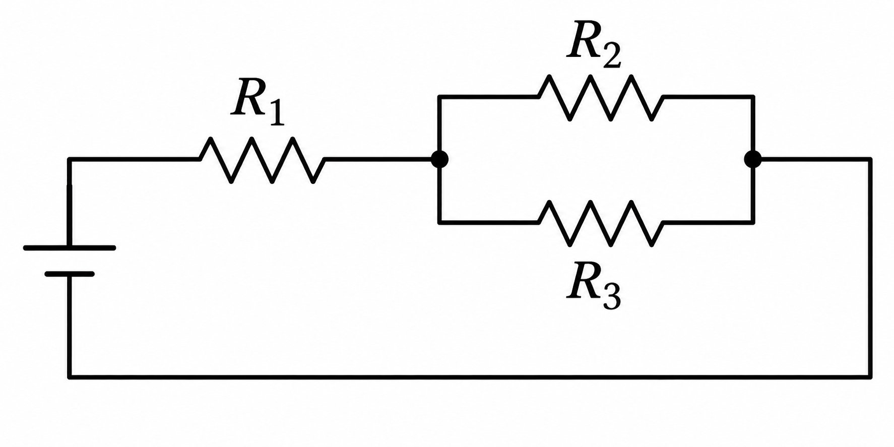
A battery and R1 in series with two parallel branches containing R2 and R3.
  1. A. 4.0 V
  2. B. 4.8 V
  3. C. 6.0 V
  4. D. 8.0 V

Question 6 of 10

An ideal 12 V battery powers R1 = 2 Ω in series with R2 = 6 Ω and R3 = 3 Ω in parallel. After a fault, the battery current is 1.5 A, the drop across R1 is 9 V, and the drop across the parallel section is 3 V. Which single change fits the measurements?

A battery and R1 in series with two parallel branches containing R2 and R3.
  1. A. R1 has increased to 6 Ω.
  2. B. The R2 branch has opened.
  3. C. The R3 branch has opened.
  4. D. R1 has been shorted.

Question 7 of 10

A 12 V battery with internal resistance 1 Ω supplies one 5 Ω external resistor. A second 5 Ω resistor is added in parallel. Which quantity increases?

  1. A. The terminal voltage.
  2. B. The current in the original 5 Ω resistor.
  3. C. The power lost inside the battery.
  4. D. The external equivalent resistance.

Question 8 of 10

An ideal 12 V battery powers R1 = 2 Ω in series with R2 = 6 Ω and R3 = 3 Ω in parallel. A 3 Ω resistor is added in series only with R3. What happens to current through the unchanged R2?

A battery and R1 in series with two parallel branches containing R2 and R3.
  1. A. It decreases from 1 A to 0.8 A.
  2. B. It stays at 1 A.
  3. C. It increases from 1 A to 1.2 A.
  4. D. It increases from 1 A to 2 A.

Question 9 of 10

Two identical resistors are connected in parallel across the terminals of a battery with nonzero internal resistance. One resistor fails open. Compared with before the failure, which statement is correct?

  1. A. Battery current falls, terminal voltage rises, and power in the remaining resistor rises.
  2. B. Battery current falls, terminal voltage falls, and power in the remaining resistor falls.
  3. C. Battery current rises, terminal voltage falls, and power in the remaining resistor rises.
  4. D. Battery current rises, terminal voltage rises, and power in the remaining resistor falls.

Question 10 of 10

A circuit has an ideal battery, R1 in series with a parallel network, and a voltmeter connected across one resistor in the network. Which change would make a finite-resistance voltmeter's reading approach the undisturbed voltage most closely?

  1. A. Decrease the meter resistance toward zero.
  2. B. Increase the meter resistance so it draws negligible current.
  3. C. Add an ideal ammeter in parallel with the meter.
  4. D. Increase the battery emf while keeping all resistance ratios fixed.